Log (By Day)
Log (By Category)
Pictures
Pics of Me Working
Links
| ||||||||||||
Monday January 29, 2007
Riveted Right Elevator
(Right Elevator)
5.0 Hours
| Previous - Index - Next |
Tonight, I set about riveting the right elevator together. It took five hours, but I got it done!
Here is the replacement E-703 rib from Vans. If you remember, I poked an extra hole in the one I was using before, so I had to borrow the one that was meant for the left elevator.
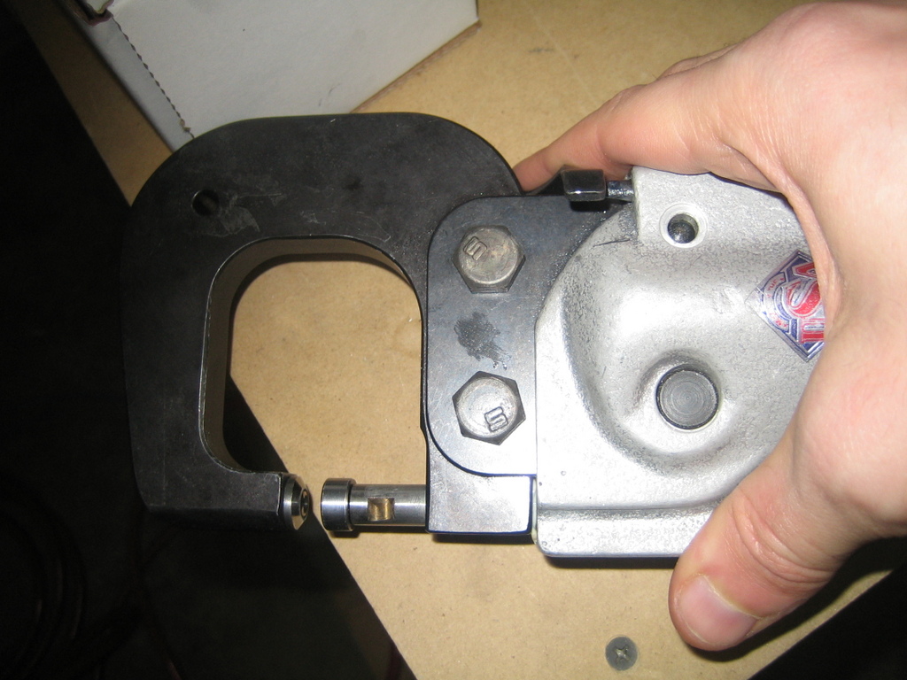
Before we get started riveting, let me show you how my pneumatic squeezer operates. You have a "yoke" that connects the squeezer body to the top part of the squeezer--it's the black part in the left side of this picture. Differently shaped yokes let you squeeze in a variety of different areas. You insert squeezer dies into the top and bottom parts of the squeezer. In this shot, I have a universal head die in the top/left part, it's also known as a "cupped" die. On the bottom/right, is a flush die that will form the shop head of the rivet.

When you pull the trigger, the bottom extends up toward the top with many hundreds or thousands of pounds of pressure. The cardinal rule of safety with this tool is to never put any part of your body in the jaws of the squeezer while it is hooked up to the air source. You could do serious bodily injury to yourself if you weren't careful.
On to the riveting: I started by riveting the two counterweight ribs together.
Before...
And after, looking at the "shop" heads. I formed these heads during the squeezing process.
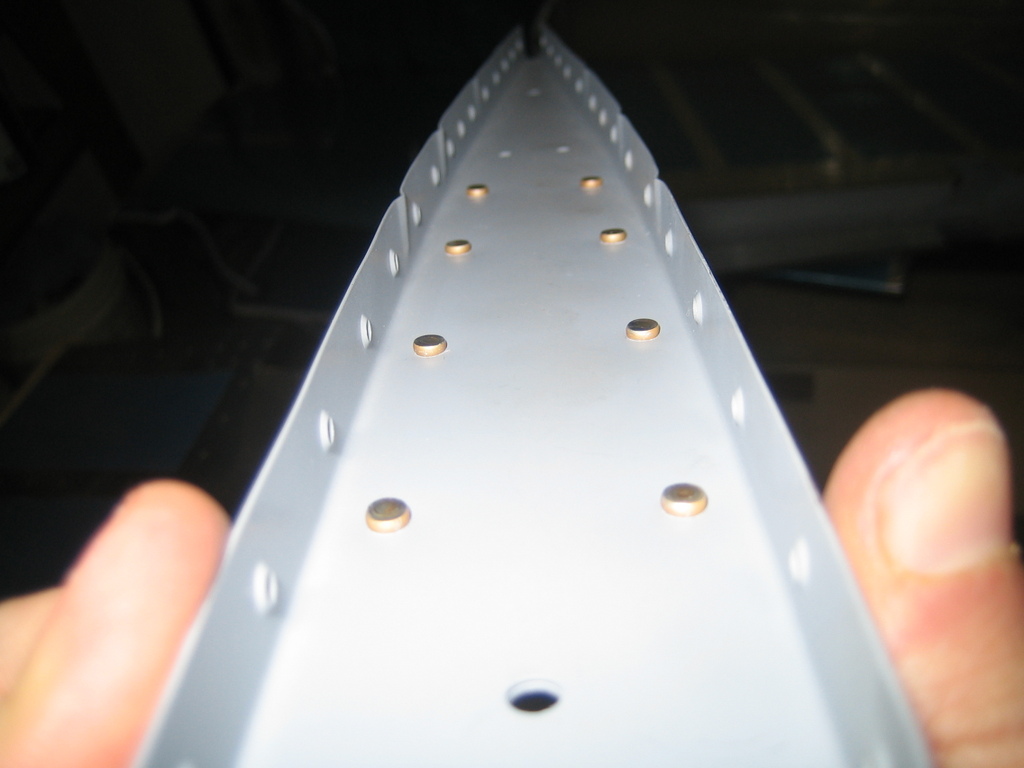
These are the factory heads that fit in the cupped die of my squeezer.
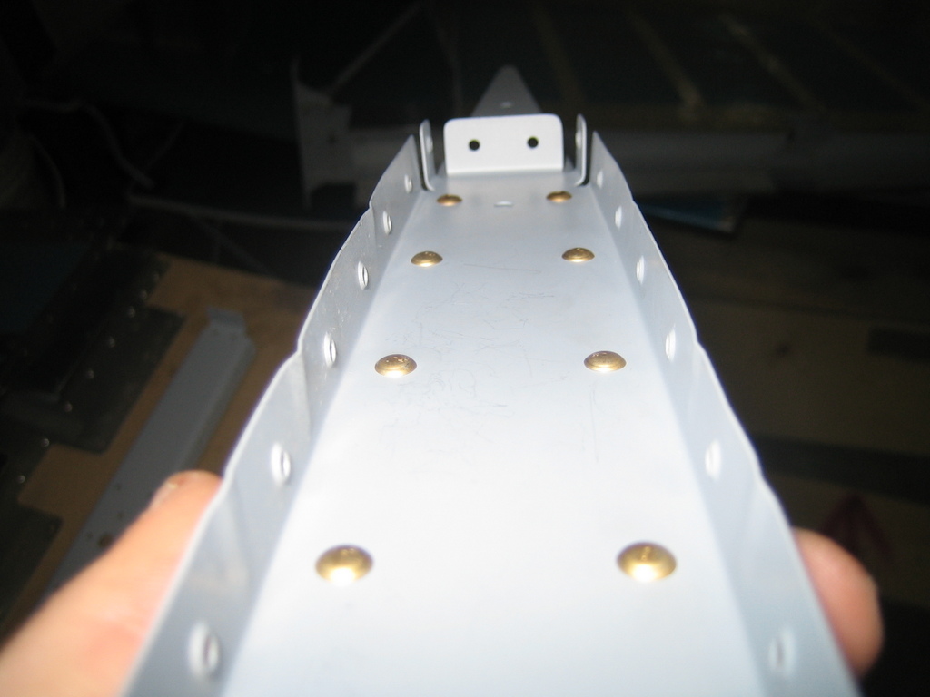
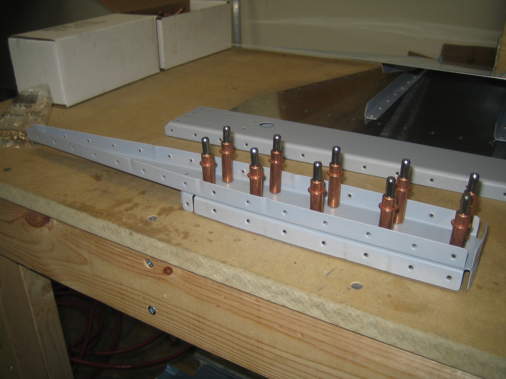
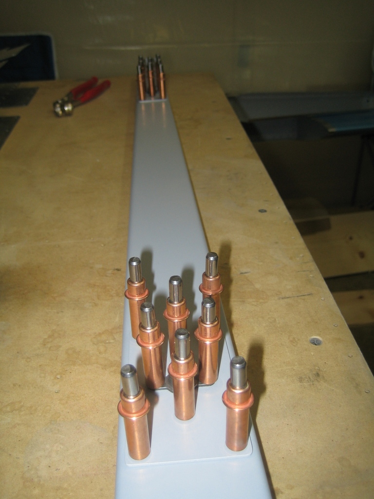
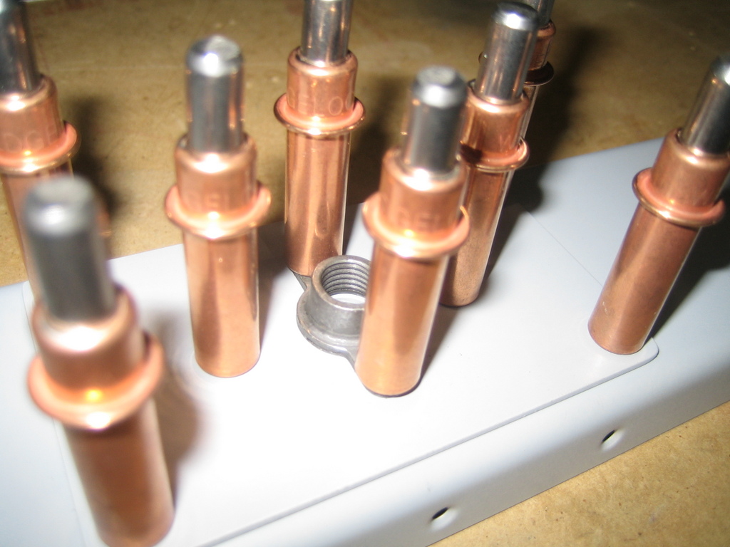
Next, I riveted the bolt attachment point stiffeners and the eye bolt nut plates to the spar.
Here they are clecoed together prior to riveting.
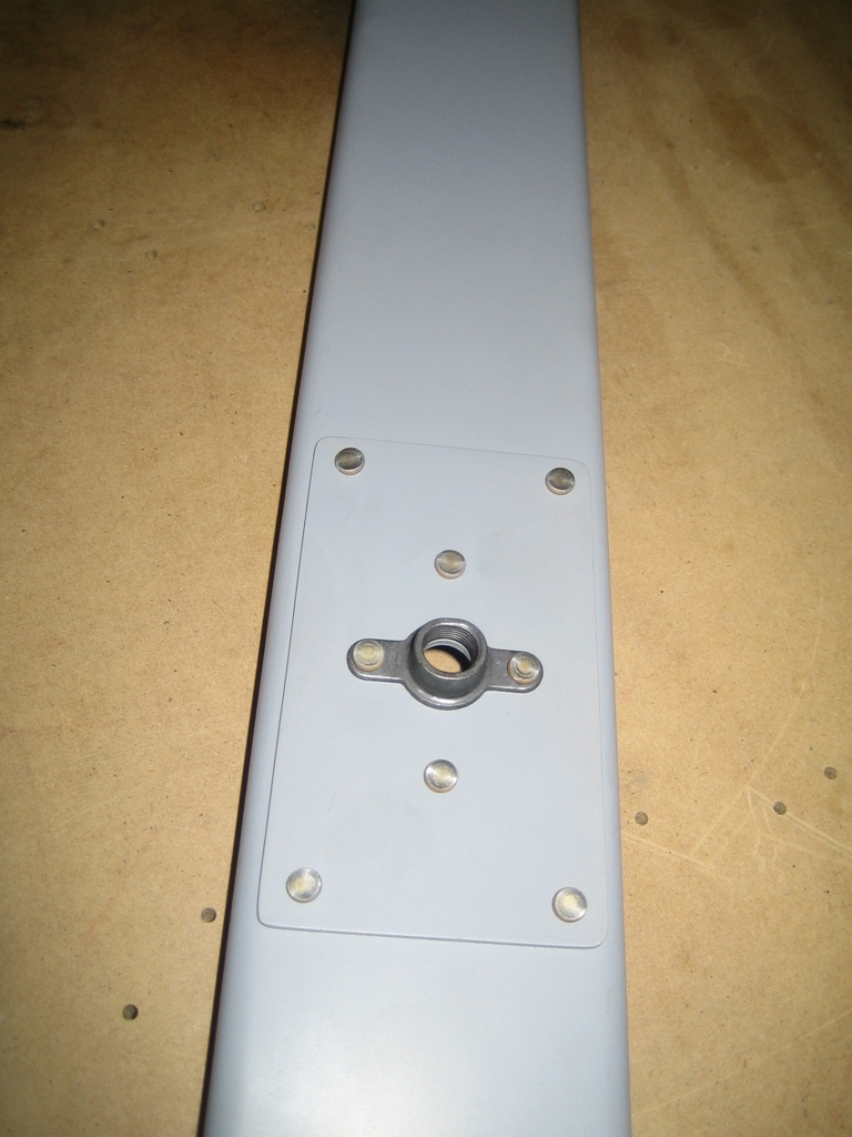
And now, riveted together.
Then, I riveted the two ribs (which I riveted together previously) to the spar. This was a fairly tricky spot to get the squeezer into, but it worked out great in the end.

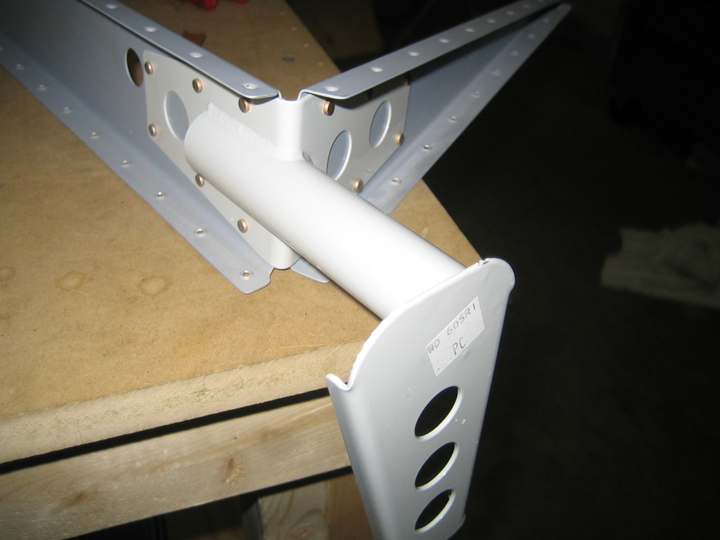
This is the control horn--it eventually gets attached to a pushrod that connects to the control stick in the cockpit of the plane. It's responsible for moving the elevator when I move the stick and is therefore very important. I first riveted the rib that you see in the background to the spar and then riveted the control horn to the spar and the rib.
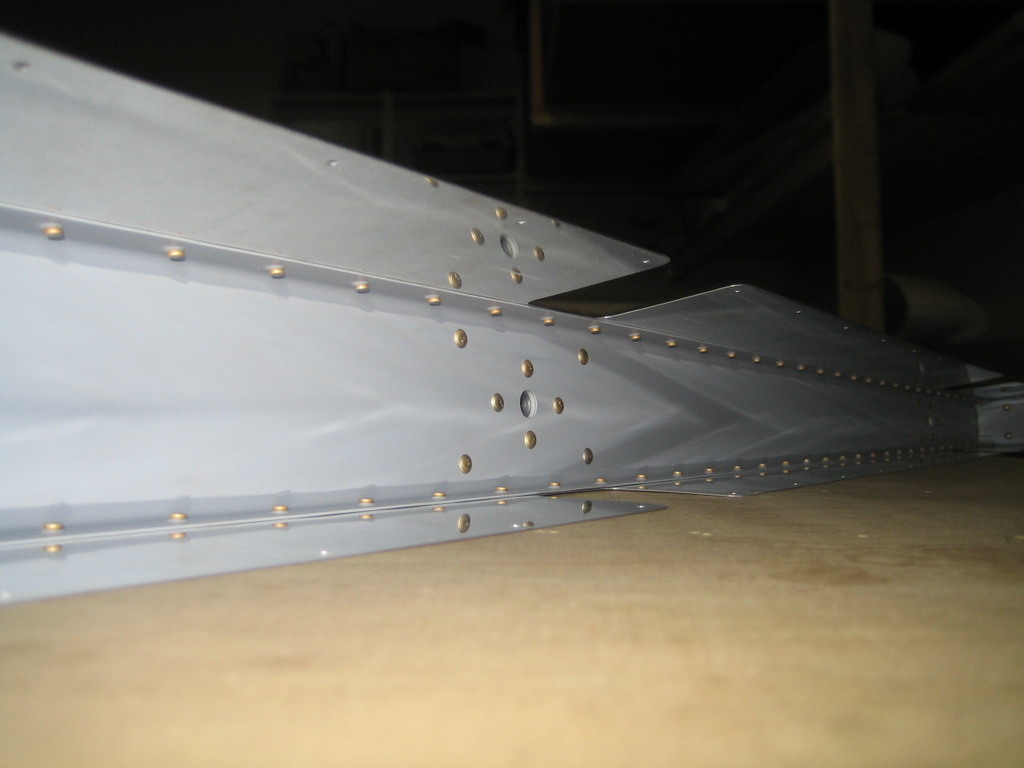
And here is the completed right elevator skeleton.

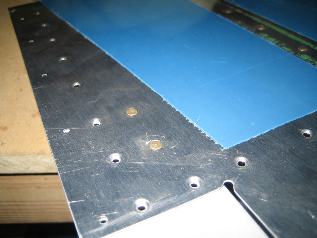
Next, the instructions have you rivet the counterweight skin to the elevator skin in four places. These would be impossible to squeeze once the ribs and spar were installed. This way, we use solid rivets instead of blind rivets.

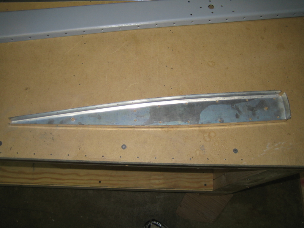
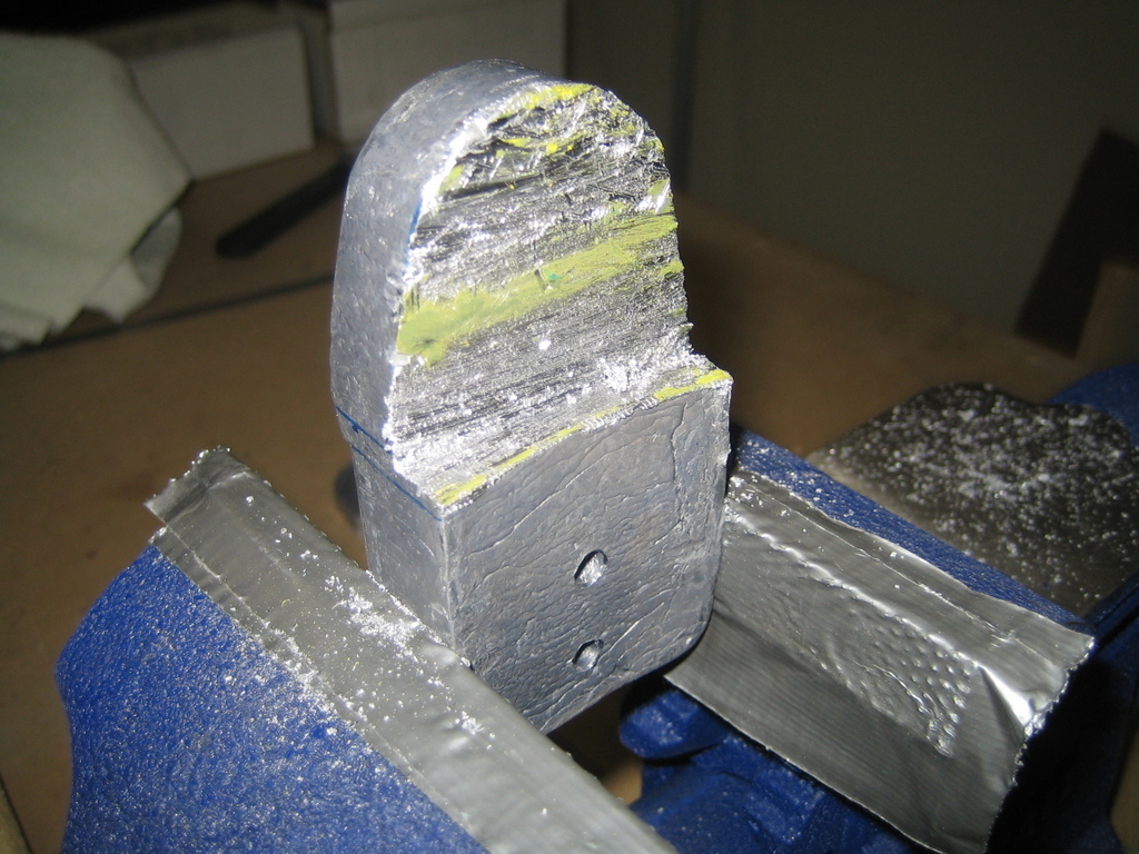
The two counterweights for the elevators ship identically. However, by the time I'm done, the left elevator, with the trim tab, related hardware, and trim tab servo, will weigh more than the right elevator. Thus, the counterweight on the right elevator needs to have less mass than the one on the left and we need to trim down the counterweight destined for the right elevator. The plans give rough dimensions to begin with and you fine tune the balance of the elevator once it's mounted and painted.
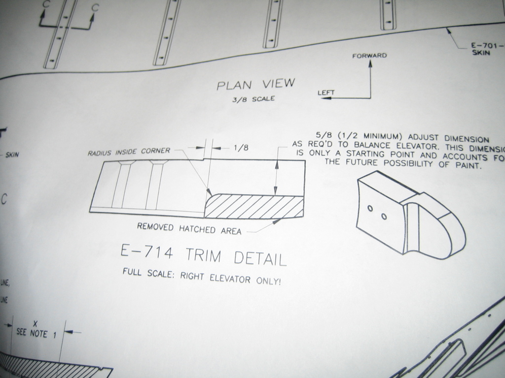
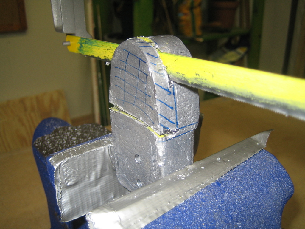
I used a hack saw to trim out the "hatched area" from the plans, but I completely forgot to radius that inside corner. I'll smooth that inside corner out later, somehow. I used some files smooth off the corners and surfaces.
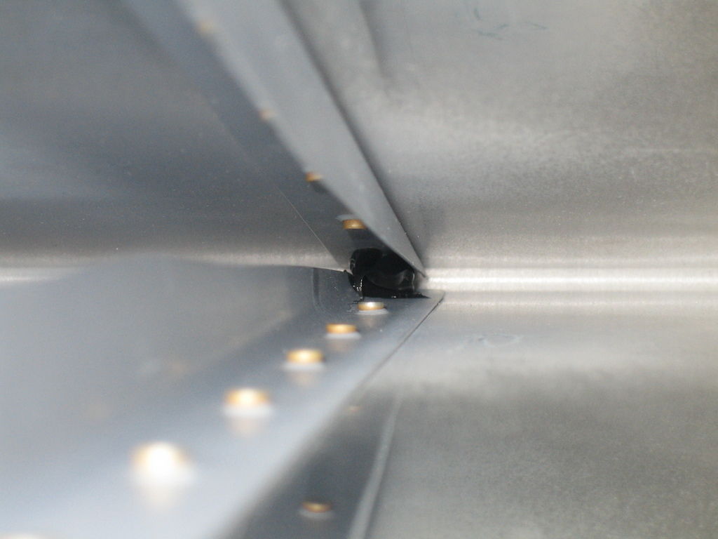
Van's instructions recommend putting a glob of RTV between the two aft rivets on the stiffeners to help prevent them from vibrating against each other during flight, so that's what I did.
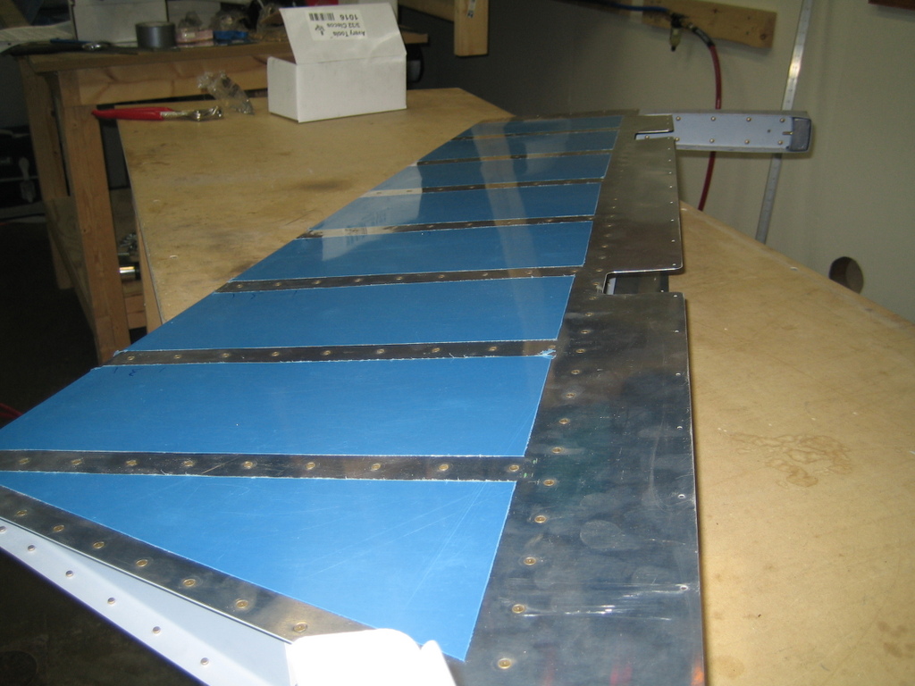
Finally, I was ready to assemble the elevator.

A few hours later, I had this.

All in all, it was an excellent night's work. All that remains on the right elevator is to form and rivet the leading edge.
| Previous - Index - Next |
This work is licensed under Attribution-NonCommercial-NoDerivatives 4.0 International![]()
![]()
![]()
![]()